
📘 ES2C-RS485 - Ethernet & WiFi to RS485 Serial with 2 Channels
Video Tutorial
RS485 Serial to Ethernet & WiFi Converter 2 Channels
1. Introduction
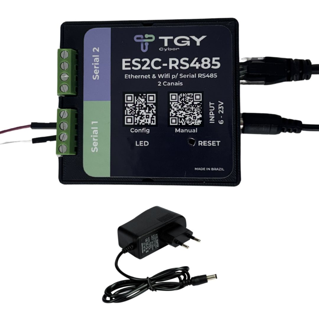
The ES2C-RS485 is an advanced serial converter from TGY Cyber designed for industrial integration. Key features include: Ethernet connectivity, expanded voltage regulator range (6 to 23V), optimized firmware for maximum stability and reliability, plus high-quality components and finish. The device has two RS485 serial ports, enabling connection of various equipment (such as PLCs, drives, sensors, energy meters and industrial scales, among others) on multipoint networks and communication via Ethernet or Wi-Fi through TCP/IP, HTTP via API, MQTT and Modbus RTU protocols.
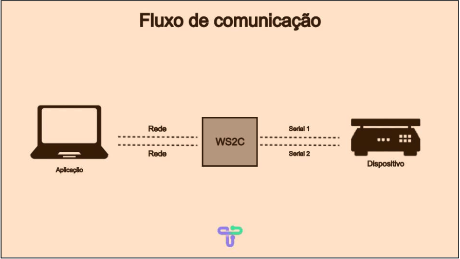
Data received from the network is transmitted to the serial port, and data sent by serial is transmitted over the network.
1.1 Installation
Connect the ES2C-RS485 to a power supply with output between 6V and 23V.
The power supply included with the ES2C-RS485 Kit operates at 127V or 220V, and the device will be ready for configuration and use.
2. Webserver
The ES2C-RS485 is configured through an internal webserver.
To access it, simply connect to the network created by the device and open your browser.
2.1 Connecting to the ES2C-RS485 network
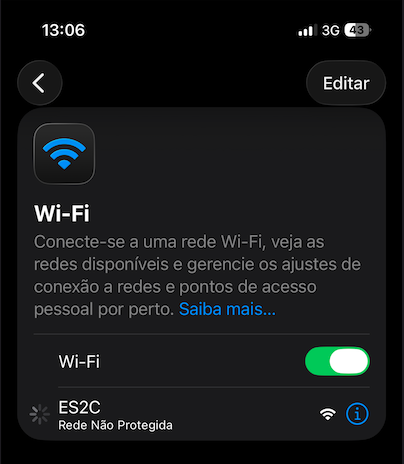
- On your computer or phone, open Wi-Fi settings.
- Find the network named "ES2C-RS485" (no default password).
- Connect, the webserver will already be available for access.
2.2 Accessing the webserver
Open your browser and type the address:
http://10.10.10.10
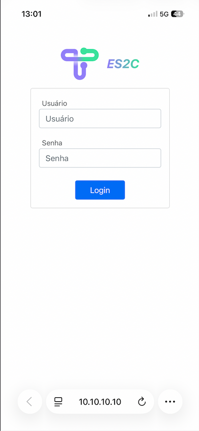
⚠️ Make sure to use "http://" and not "https://", as the server does not support HTTPS.
2.3 Logging into the webserver
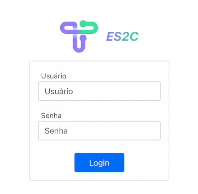
The login screen will display the following fields:
| Field | Default value |
|---|---|
| Username | admin |
| Password | admin |
3. Configuring the device
The webserver has five sections:
- System configuration
- Serial port configuration
- General configuration
- Status view
- Protocol configuration
3.1 System configuration
In this section you can adjust:
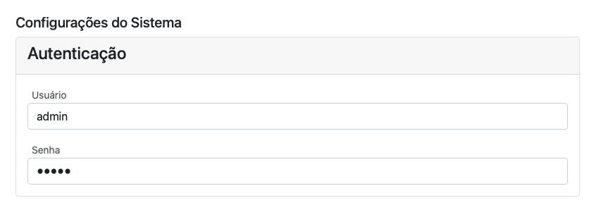
- Authentication data (webserver username and password)
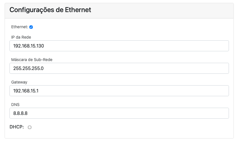
- Ethernet network settings (DHCP or manual)
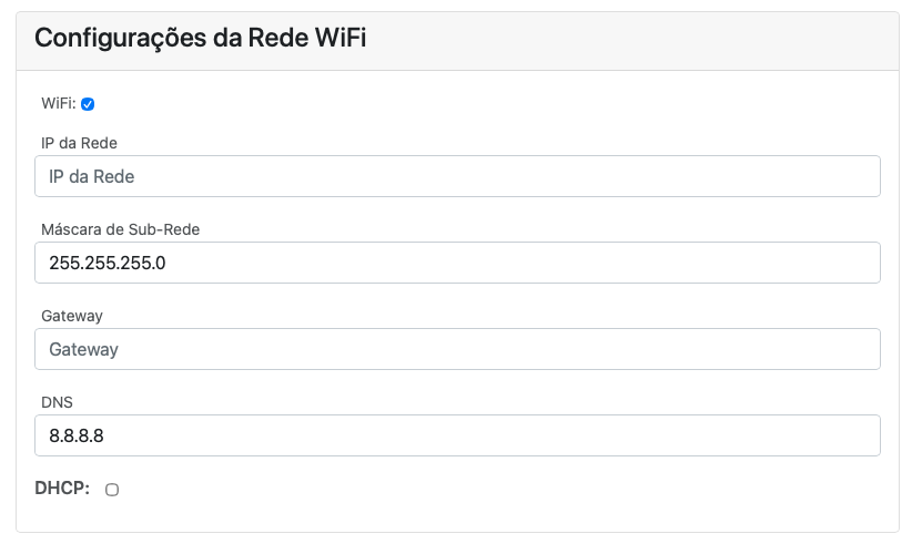
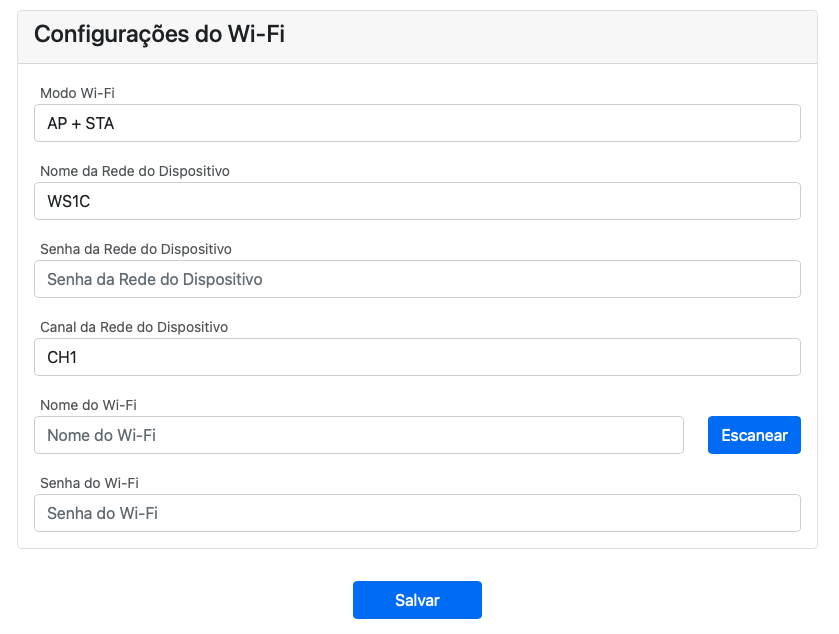
- Wi-Fi network and operation settings
LAN Configuration
| Field | Description |
|---|---|
| Network IP | Fixed IP address (if manual mode) |
| Subnet mask | Default: 255.255.255.0 |
| Gateway | Router address |
| DNS | Default: 8.8.8.8 (Google) |
| DHCP | Can be enabled or disabled |
⚠️ Disabled DHCP mode is recommended to avoid IP changes and loss of communication.
Wi-Fi Configuration
| Field | Description |
|---|---|
| Wi-Fi Mode | AP + STA, AP, or STA |
| Network name | SSID displayed in Wi-Fi search |
| Password | Wi-Fi connection password |
| Channel | Default "1" or values between 1-13 |
📶 AP (Access Point): Creates the ES2C-RS485 network for configuration.
📡 STA (Station): Connects the ES2C-RS485 to the local Wi-Fi network.
🔁 AP + STA: Allows simultaneous configuration and operation (recommended).
| Channel | Frequency |
|---|---|
| 1 (Default) | 2.412 GHz |
| 2 | 2.417 GHz |
| 3 | 2.422 GHz |
| 4 | 2.427 GHz |
| 5 | 2.432 GHz |
| 6 | 2.437 GHz |
| 7 | 2.442 GHz |
| 8 | 2.447 GHz |
| 9 | 2.452 GHz |
| 10 | 2.457 GHz |
| 11 | 2.462 GHz |
| 12 | 2.467 GHz |
| 13 | 2.472 GHz |
3.2 Serial port configuration
The ES2C-RS485 has two independent serial ports, configurable individually.
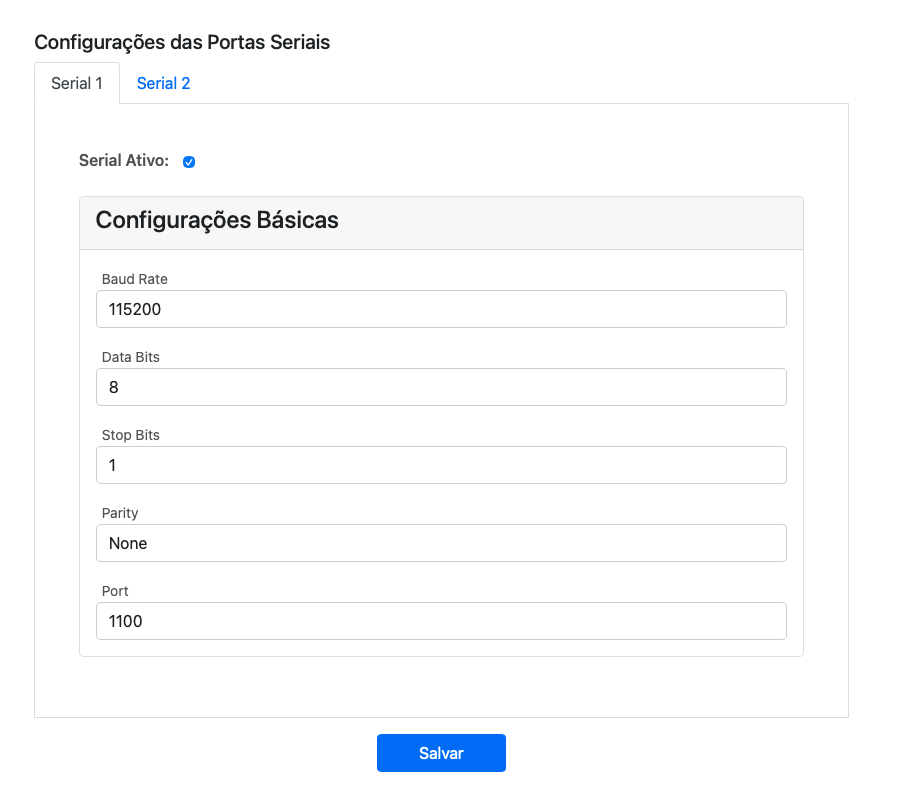
| Parameter | Description |
|---|---|
| Baud Rate | Communication speed. Supported values: 1200, 2400, 4800, 9600, 19200, 38400, 57600, 115200, 250000, 921600 |
| Data Bits | Data bits |
| Stop Bits | Stop bits |
| Parity | Parity type |
| Port | TCP/IP port associated with serial |
By default:
- Serial 1 → Port 1100
- Serial 2 → Port 1101
⚠️ Ports cannot be the same.
Each serial port can be enabled or disabled as needed.
3.3 General configuration
This tab contains the basic system options:
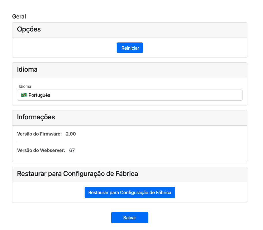
| Option | Function |
|---|---|
| Restart | Restarts the converter |
| Language | Portuguese / English |
| Factory Reset | Returns to original settings |
⚠️ Resetting the system erases all user configurations.
3.4 Saving data
After configuring each section, click "Save".
A success message will be displayed at the top of the page.
Restart the ES2C-RS485 to apply the changes.
⚠️ To restart the converter, quickly press the physical reset button once.
Attention: Do not hold the button for more than 10 seconds, as this will cause the converter to return to factory settings.
3.5 System Status
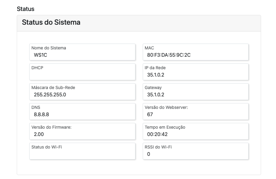
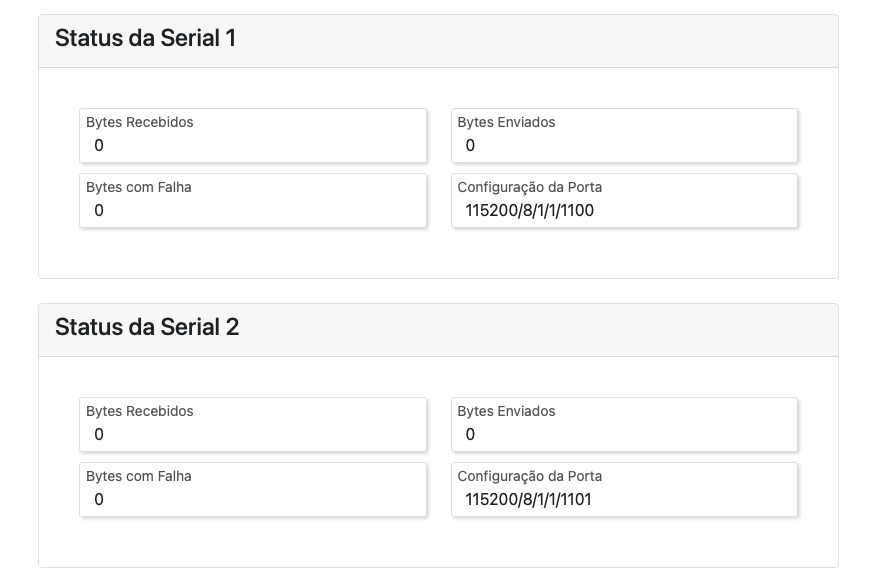
Displays information such as:
| Parameter | Example |
|---|---|
| System Name | ES2C-RS485 TGY |
| MAC | 70:B8:F6:5C:BE:BC |
| IP | 192.168.15.11 |
| Mask | 255.255.255.0 |
| Firmware Version | 1 |
| Webserver Version | 1 |
RSSI (Wi-Fi signal strength)
| Value (dBm) | Quality |
|---|---|
| 0 to -50 | Excellent |
| -51 to -60 | Good |
| -61 to -70 | Acceptable |
| -71 to -80 | Weak |
| -81 to -100 | Poor |
Also displayed is the total bytes sent and received by each serial port via the TCP/IP protocol.
3.6 Protocols
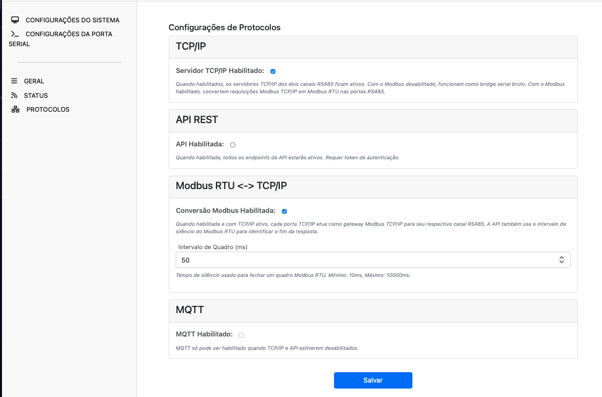
In this tab, you can enable or disable the communication protocols supported by the ES2C-RS485: TCP/IP, API (HTTP), MQTT and Modbus RTU.
To ensure greater system stability, it is recommended to enable only the protocols that are actually needed. By default, only the TCP/IP protocol is enabled. The MQTT protocol can only be enabled if both TCP/IP and API protocols are disabled.
4. Physical interface of the device
The ES2C-RS485 has:
2 RS485 serial ports — A+ and B- terminals (differential communication, ideal for industrial multipoint networks)
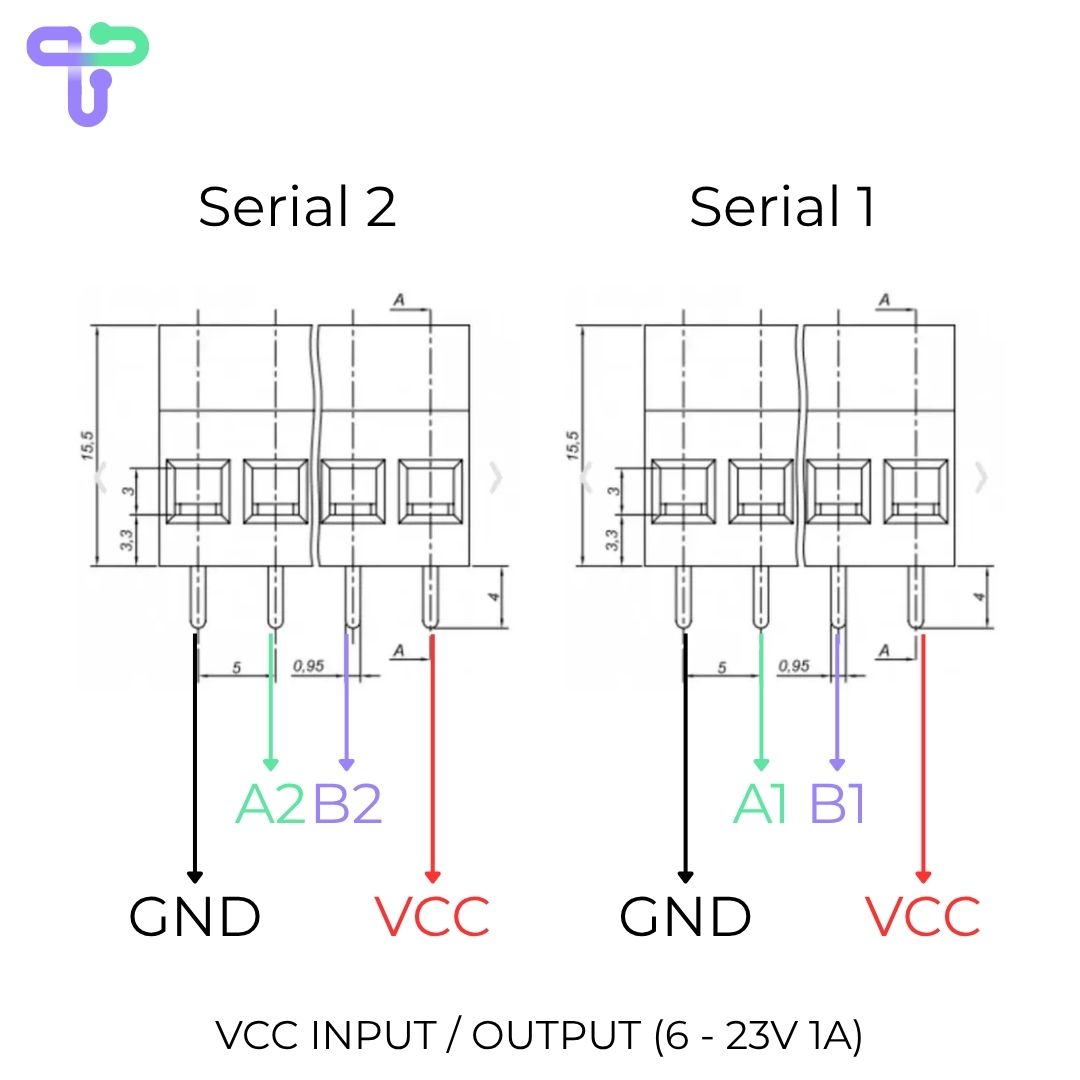
For long RS485 networks or networks with many devices, check whether termination resistors are required according to the connected equipment manual.
1 reset button
1 indicator LED
4.1 Button
| Action | Function |
|---|---|
| Quick press | Restarts the system |
| Hold pressed (10s) | Restores factory settings |
4.2 Indicator LED
| LED State | Meaning |
|---|---|
| Fast blinking (200ms) | Error — requires restart |
| Slow blinking (1s) | Normal operation |
| Irregular blinking | System updating |
| Fixed on | Initializing |
| Off | Powered off |
5. Testing Software
The TGY Cyber Suite is recommended software for testing and validating ES2C-RS485 serial communication.
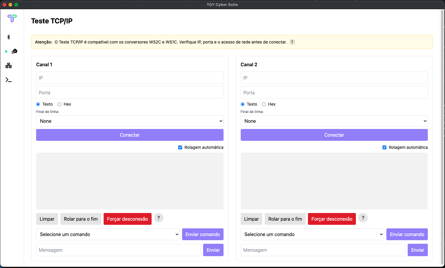
After downloading the software, you can see how to test the communication by watching the video below:
⚠️ Follow the procedure shown in the video to validate ES2C-RS485 communication.
Steps:
- In the TGY Cyber Suite software, access the TCP/IP Test tab
- Connect the loop connector to the ES2C-RS485 as shown in the video.
- Enter the IP and serial port.
- Click Connect.
- Type a message and send.
- If there is loopback between pins 2 (RX) and 3 (TX), the text will return in the reception field.
6. API - Application Programming Interface
The ES2C-RS485 provides a REST API that facilitates integration with various external systems and applications.
Activation or deactivation of the API can be performed in the protocols menu, as explained in section 3.6 of this manual.
Watch the video below to see how to use the API in practice:
⚠️ All requests require an authentication token (minimum 6 digits).
6.1 Endpoint: /post-serial-data
Returns data received by the serial port in JSON format.
Example request:
URL:
POST http://192.168.15.130/post-serial-data
Header:
Authorization: 123456
JSON Body:
{
  "port": 1100,
  "time": 2500,
  "command": ""
}
port: port to listen totime: listening time (ms)command: optional command to send before listening
cURL:
curl -X POST http://192.168.15.130/post-serial-data \
  -H "Accept: application/json, text/plain, */*" \
  -H "Content-Type: application/json" \
  -H "Authorization: 123456" \
  -d '{"port":1100,"time":500,"command":"\u0005"}'
You can validate the API functionality with the TGY Cyber Suite software
⚠️ Listening time below 30 seconds is recommended to avoid blocking other functions.
7. MQTT - Message Queuing Telemetry Transport
The ES2C-RS485 offers MQTT protocol support, providing an efficient solution for cloud application integration and IoT automation. Configuration to enable or disable MQTT can be easily performed through the protocols menu, as detailed in section 3.6 of this manual. Check out the video below for a practical demonstration of how to use MQTT with your ES2C-RS485:
8. Modbus RTU
The ES2C-RS485 offers native support for the Modbus RTU protocol, enabling integration of Modbus-compatible industrial devices with supervision systems, SCADA and IoT applications via Ethernet or Wi-Fi.
Modbus RTU can be enabled or disabled in the protocols menu, as described in section 3.6 of this manual.
8.1 Operation
In Modbus RTU mode, the converter acts as a gateway, forwarding Modbus RTU requests received over the network (TCP/IP) to the configured RS485 serial port and returning responses to the requester.
8.2 Configuration parameters
| Parameter | Description |
|---|---|
| Slave address | Modbus address of the device connected to the serial port (1 to 247) |
| TCP port | Network port associated with the Modbus RTU channel |
| Baud Rate | Must match the slave device configuration |
| Parity / Stop Bits | Must match the slave device configuration |
⚠️ Ensure RS485 serial port parameters are identical to those of the connected Modbus equipment.
8.3 Compatibility
ES2C-RS485 Modbus RTU is compatible with standard Modbus functions used by PLCs, variable frequency drives, energy meters and other industrial equipment operating over RS485.
For greater stability, enable only the protocols you actually need. Modbus RTU can operate independently or together with TCP/IP, depending on webserver configuration.